BierBot Brick
The "Brick" has a temperature sensor and a relay that allows you to control the mash tun, refrigerator or fermenter.
How to get one?
you can either buy one
or build one yourself (see below).
How to build you own BierBot Brick
What you'll need
You don't need much to build your Brick, most of the tools are optional (and just make your life easier).
Materials
Sonoff TH16 incl. a temperature sensor - this is the main component.
Tools
USB Serial converter (Virtual COM-Port) - to flash the PCB.
mini USB cable (if you don't already have one) - to connect your serial converter to your PC.
Something to strip the wires (pliers, scissors, knife, etc.).
Two screwdrivers (philips and longitudinal slot).
Optional: wire end ferrules and a wire end ferrule pliers.

Steps
Step 1: Expose the contacts
First we have to expose the contacts of the board, via which we will then flash the software.
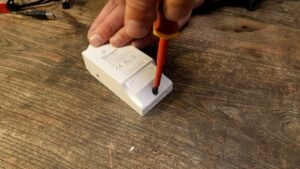
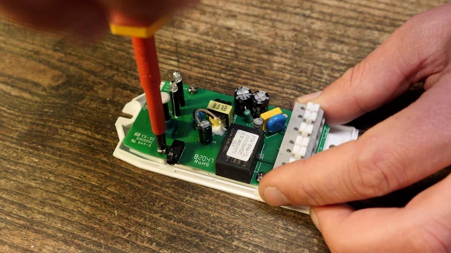
To do this, first loosen the Phillips screw and lift off the front cover (Figure 1.1). Then insert a teaspoon between the upper and lower part of the housing at the U-hole. By turning the spoon, the housing can now be pried open (Fig. 1.2). Now you only have to loosen the 4 screws that secure the circuit board in the housing (Figure 1.3).

Step 2: Soldering the DIP pin header
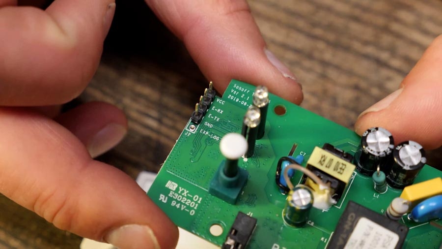
There are 5 DIP holes on the board with which we have to make "contact" for flashing. For this we simply solder the 4x1 pin header. Important here: We only need the pins from "GND" to "VCC" ("EXP-LOG" is not needed). Insert the pin header from the top, turn the board around and solder it from the bottom with 4 solder pads. Soldering tip: Rather heat the contact surfaces on the board, and then dab the solder to it.
Now screw the board back into the lower part of the housing using the 4 screws.

Step 3: Connecting the power cable
Now you need the extension cable. Cut it (Figure 3.1) (the center is not necessarily the best place for your purpose), and carefully remove the insulation (Figure 3.2 and 3.3). When removing the outer insulation (black in our case), be careful not to damage the inner insulation (brown, blue, yellow-green). Repeat the process for both ends of the cable.


Now thread the cable through the opening of the upper housing part (Fig. 3.4) from "outside" to "inside" (in quotation marks, because the housing is currently open). Twist the strands together. If available, you can also crimp a wire end sleeve (ideally with a 4-jaw pliers to maximize the contact area).
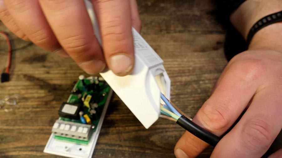
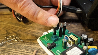
Now connect the wires to the terminal of the board (Figure 3.5 and 3.6). For this purpose, it is best to press on the top of the button with a longitudinal slot and insert the cable. The board must be completely de-energized during this step! In no case connect the plugs with the socket!


The mapping is as follows:
Label on PCB
Plug/Socket
Cable Color (Germany, EU)
US
L IN
Plug
Brown
Black
L OUT
Socket
Brown
Black
N
doesn't matter
Blue
White
Epsilon / E
doesn't matter
Yellow-Green
Green-Yellow
On the Figure 4.3 you can see a clear representation for EU color coding.
Step 4: Connect the data cable for flashing
Now it's time for the "Rainbow" cable. We use it to connect our pin header (Figure 4.1) to the serial interface (Figure 4.2). Connect the Rainbow cable "as is" to the pin header of the board. Make sure that the jumper on the serial interface is set to 3.3V when it is "right" (when the USB port is up).


The other side must be connected to our USB board. Pay attention to the labels! Start with GND, that belongs on the outside. Now leave one pin free. Now comes "VCC" (in our case white, the cable that is maximum away from GND on the board), followed by E-RX (black) and E-TX (brown) - so in the same order of the pin header.
For your reference: Here again the complete cabling (power and data cable)

Step 5: Flashing the Software
Now we still have to play the software on our board. For this we need two things:
The Brick software itself (available for free on Github). Download the "firmware.bin" of the "Latest Release".
The tool to flash the chip (ESP8266) (also available for free on Github). Most likely you need the ESP8266Flasher.exe file from the "Win64/Release" directory.
Save both files (Flasher and firmware.bin) on your PC. Now connect the USB board with the mini USB cable to your PC. To check if the board is recognized correctly do the following: Press the Windows key (on your keyboard), type "Hardware", click on the Hardware Manager. Under "Ports (COM & LPT) you should now see a COM3 (or any other number).
Now start the "ESP8266Flasher.exe". Go to the tab "Config" ( (1) in the picture), and click on the gear wheel ( (2) in the picture). Select the "firmware.bin" in the dialog that pops up.

Go back to the "Operation" tab, select your COM port (in my case "COM3").
Now we have to put the board into flash mode. For this we start with a powerless board (unplug the mini USB from your PC). Then hold down the button on the board 1), and then connect 2) (while holding down the button) the mini USB cable to the PC again.
Hit Flash! The Flashing tool will now install the PCB with the software - time to get some homebrew to celebrate this victory!

Step 6: Closing the case
As soon as the flashing tool signals the successful completion of the flashing process with a green checkmark, we now only have to reassemble the case. To facilitate future updates, it is recommended to route the Rainbow cable with "outside" and leave it plugged on the DIP header (but take a photo or label of the GND cable for future reference). Please note that you should protect the case from water, as it does not meet IP68 in this state.

Click the case back together & plug in the DS18B20 temperature sensor - Done!
Final words
You can now head over to bricks.bierbot.com and setup your Brick and at it to a device. And explanation how to do so can be found here.
This howto will be also available on ![]() German on the awesome brau!magazin.
German on the awesome brau!magazin.
⚠️ DISCLAIMER: DANGER OF ELECTROCUTION ⚠️
If your device connects to mains electricity (AC power) there is danger of electrocution if not installed properly. If you don't know how to install it, please call an electrician (Beware: certain countries prohibit installation without a licensed electrician present). Remember: SAFETY FIRST. It is not worth the risk to yourself, your family and your home if you don't know exactly what you are doing. Never tinker or try to flash a device using the serial programming interface while it is connected to MAINS ELECTRICITY (AC power).
We don't take any responsibility nor liability for using this software nor for the installation or any tips, advice, videos, etc. given by any member of this site or any related site. source
Last updated
Was this helpful?